...in your car...
The Bedroom Vehicle: Solar Power Overview Technical Assistance Provided By Bob Wright:
Hello. I'm Bob Wright. I've worked for over 38 years as an electrician. I'm retired now but my brain isn't, so if you have any questions about any of this feel free to leave me a message on my cell phone at: 925.200.8313 and I'll do my best to try to help. The drawings I'm explaining are:
Why install a solar power system in your vehicle?
The purpose of installing a solar power system in your vehicle is to provide almost constantly available AC, 120-V power in your car so that you can use typical low-wattage home applicances in your vehicle, making you more self-sufficient. For example, you will be able to operate most electronic devices and low-wattage kitchen appliances that together do not exceed the capabilities of the solar power output through your inverter, as stored in your storage battery.
However...
However this means that most hot plates will exceed this limit. Pamela was not able to find one that uses less than 750 watts of power and the maximum recommended power draw for her system is about 600 watts for a half hour.
A couple cautions:
Another issue to be kept in mind as you read these general instructions is that any connections or wiring could become a fire hazard if not made or installed correctly. Loose connections result in arcing and the build-up of heat. If you are not familiar with how to join wires together using wire nuts in such a way that the splice is tightly made as if it were a single wire, then you'll probably have to barter with an electician friend for this service. Making electrical connections is not a job to be learned as you go. Learn how first.
Also: You must be very careful in handling any battery. You do not want the 12 V DC to complete a circuit through you, to travel from positive to negative through your body. So, for example, when you bring your power feed from the supply battery to the inverter, these wires are hot - do not touch the bare copper of both simultaneously.
And it's important to read carefully the instructions that come with the inverter.
Solar Power Set-Up:
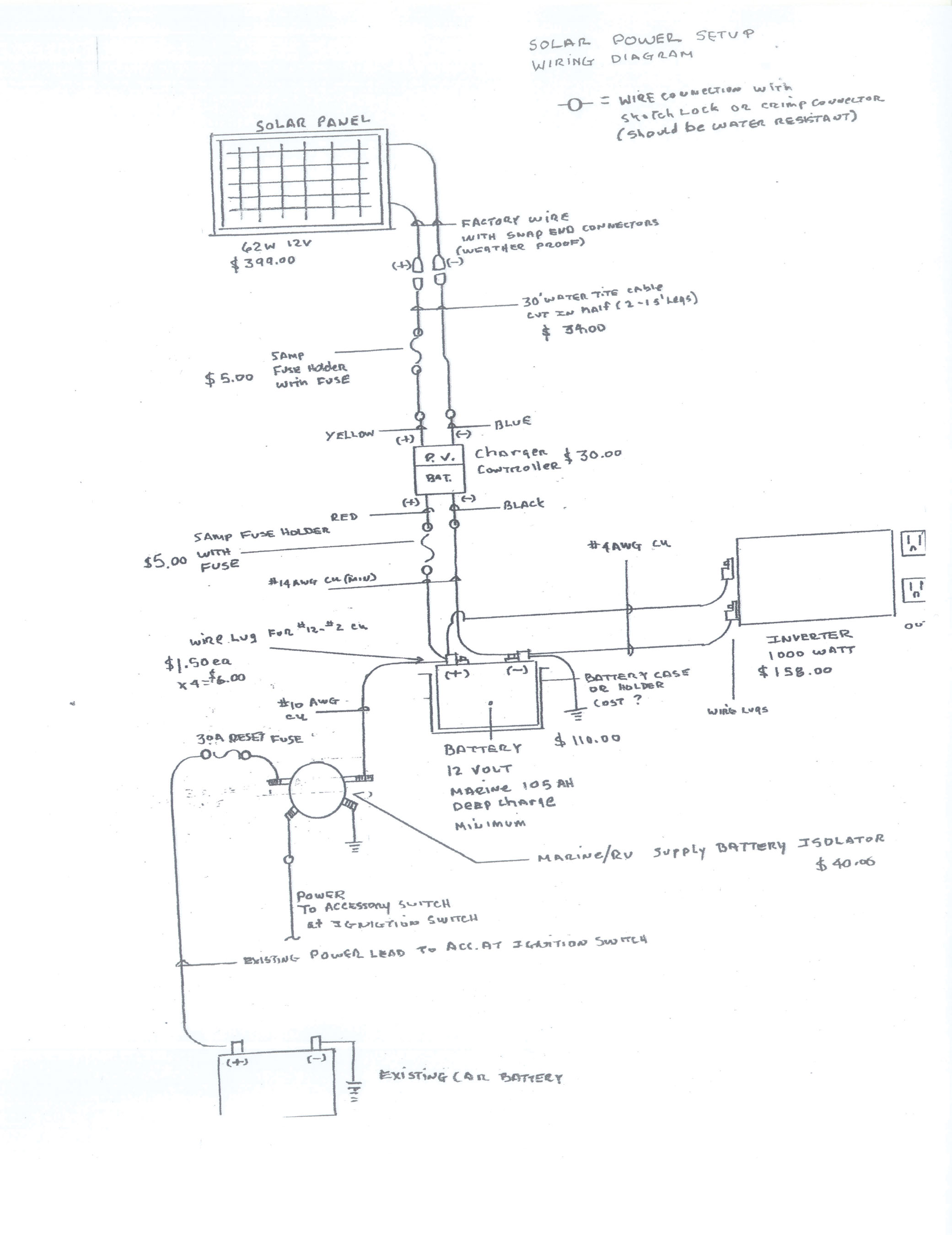
The drawing called Solar Power Set-Up explains the parts and pieces needed to make your self-suficient solar power system for your vehicle. The parts consist of: the solar panel, the charger / controller, the storage battery, the inverter, and the supply battery isolator. You will also need - in addition to the 30 foot cable with water-tight snap ends, purchased with the solar panel - to purchase three (3) in-line, protective fuses, the wire to tie the system together, and the connectors to connect the system. This wiring diagram shows you the correct wiring, and hopefully the other supplemental drawings will show you how to attach all of these parts. Exact locations of each piece are not shown as they will vary by vehicle and your application. For example, there may not be room under the hood of your car for the storage battery and you may decide to put it in the passenger footwell, or some other location.
The solar panel:
The solar panel provides the initial DC voltage input by gathering energy from the sun in the solar cells and converting it to DC power. This output power is protected by the 5-amp fuse in the positive lead from the panel.
The charger / controller:
This output is connected to the charger / controller. The charger / controller has two sides. The input side of the charger / controller is marked "PV" for "photovoltaic." You will see two leads out of this side. One is yellow (positive) and the other is blue (negative). These attach to the positive and negative wires from the solar panel using the 30 foot cable purchased with the solar panel.
The other side is marked "battery" and has red (positive) and black (negative) wire leads. These attach to the wires that will go to the storage battery. Make sure that the red-positive wire is protected by an "in-line" (that is to say, before it gets to the battery) 5-amp fuse. Coming out of the charger / controller you will need minimum #14 AWG copper to run from the charger / controller to the storage battery - the length to be determined by the location of the controller and the battery. Once again, the positive wire coming out of the battery-side of the controller will need to be protected by a 5-amp fuse before it gets to the battery. Again, using #14 AWG copper with length determined by locations.
The storage battery:
The storage battery should NOT be a regular automotive battery. It needs to be a marine or deep charge battery sized both to your needs and to the solar output. It can probably be purchased where you buy the solar panel.
Batteries are rated in number of amp-hours. The higher the amp-hours the higher the storage (or power available per hour.) For example, the output of Pamela's panel is 67 watts or 5.58 amps. (This amps figure is found using Ohm's law, or watts divided by the 12 volts.) Her 106 amp-hour battery requires about six hours of direct sunlight to charge. 106 amp-hours is sufficient for her minimal anticipated usage because she will not have any continuous loads. Be aware that you cannot fully drain any battery and usage must be gauged according to about half the amp-hours available in the battery, so her approximately 50 amps within an hour can be stretched out over the entire day. If you had no recharging capability (meaning, no direct sunlight or car-charging), you would have 50 amps in an hour to use - or, for example, a 100-watt crock pot at 120 V could run for 50 hours, as it only draws one amp. A laptop computer could run indefinitely.
The mounting of the battery requires a battery rack or battery box, purchased separately (normally found at automotive supply stores.) Ideally the storage battery would be located in the engine compartment. If the battery needs to be placed inside the vehicle, a covered battery box is necessary. There is no danger of the battery exploding, however it may emit fumes (in circumstances of a deep charge or if you're using it to jumper someone else's car, which you would never do.) The water level should be checked on a bi-weekly basis, and, if low, topped off with distilled water only.
Coming out of the battery you will need to wire the DC power to the inverter which will change it magically into AC power.
Output to the inverter:
All the wiring prior to the battery is low-amperage input. However, the wiring that comes out of the battery is your high-amperage output that powers your loads (the appliances, lights, and electronic devices). Because amps mean heat, you will need much larger wire to carry the current for your loads. For example in Pamela's case the output to the inverter could be as much as 80 amps so she will need #4 AWG size wire, length to be determined by locations of the battery and inverter.
The extra wiring you need to purchase beyond the initial sheathed cable provided when you buy the solar panel will need to be protected from physical damage. This means securing it, for example, along the floor board if internal to the vehicle or to the frame rails under the vehicle. This does not mean sheathing the wire, but rather fixing it in place. However all penetrations should be protected with some form of grommet or sheath.
For connections at the battery and the inverter, it will be necessary to purchase wire lugs to fit the threaded studs on the battery and the inverter.
The inverter includes internal protection and a display that registers either watts or volts.
The supply battery isolator:
The system as described is a stand-alone system that is recharged solely by the solar panel. This makes it totally dependent on available sunlight to recharge the battery. With excesive use the battery may get depleted faster than the panel can recharge it. So, as an alternative recharging source we are also using the charging system of the vehicle itself. In order to prevent the car battery from being used to power this auxiliary solar system it must be isolated from it. This is done using a device called an isolator (on the drawing it's labeled "Marine / RV Supply Battery Isolator"). The isolator is best located by the vehicle battery. You should check with your auto mechanic to find the location of the primary battery lead that is fuse-protected that runs your car battery (that is charged by the alternator). Once you've found this wire then you can determine the placement of the isolator.
The isolator will have a bracket with holes in it to allow it to be screwed onto the metal wll of your engine compartment. You will need to take a #10 AWG wire (purchased separately) from the battery lead as identified by your mechanic to the first terminal on the left of the isolator. This should be protected with a 30-amp in-line fuse.
[Drawing clarification: the wire labeled as "existing power lead to accessory switch at ignition switch" is acutally the lead identified by your mechanic. The other terminal on the left of the isolator labeled "Power To Accessory Switch At Ignition Switch" is not used.]
The next terminal clockwise on the right goes to the chassis ground. This means taking a #10 AWG wire from that terminal to a metal portion of the car and screwing it to that metal using a bolt, a self-tapping screw, or a lug. This area should be scraped or sanded so there's a good metal surface for contact. This wire should be fixed in place.
The last terminal (upper right) is the power lead and goes to the positive terminal of your storage battery. Attach a ring lug to the end of this wire using crimpers, then place the ring on the positive terminal post under the wire (already there) of the storage battery. Make sure all connections are very tight.
This completes the alternate charging system.
Solar Power Overview:
The Bedroom Vehicle